Bearing Replacement on Eleven Heavy Haul Rail Bridges for Roy Hill

LEC have been a key technical advisor to Roy Hill throughout their ongoing heavy haul rail bridge bearing replacement program, from feasibility desktop studies through to advanced finite element analysis and bearing replacement.


DESKTOP STUDY OF HEAVY HAUL RAIL BRIDGES

Roy_Hill_Rail_1.jpg

FOCUSING QUESTION

Would it be feasible for the existing rail bridges to withstand an increased axle load and thus enable Roy Hill to increase their rail haulage capacity whilst utilising their existing infrastructure?

Roy_Hill_Rail_2.jpg

THE SOLUTION

LEC undertook a desktop study of three selected bridge spans to determine the maximum load carrying capacity of the existing waterway and overpass steel girder rail bridges along Roy Hill’s mine-to-port rail corridor.  Design checks of the main bridge components were carried out for strength (i.e. bending & shear) and serviceability.

THE LEC ADVANTAGE

Based on the outcome of the desktop study, LEC were able to advise Roy Hill of several opportunities that could be explored to increase the axle load on the bridges, such as detailed assessment using finite element analysis (FEA), site deflection & strain gauge measurements to determine the actual Dynamic Load Allowance (DLA), and de-rating of the bridge design load factors.


DETAILED ANALYSIS OF HEAVY HAUL RAIL BRIDGES

Roy_Hill_Rail_3.jpg

FOCUSING QUESTION

Determination of the actual Dynamic Load Allowance (DLA) for selected heavy haul rail bridges.

THE SOLUTION

Roy_Hill_Rail_4.jpg

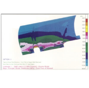
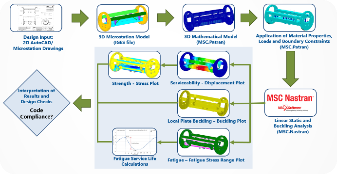
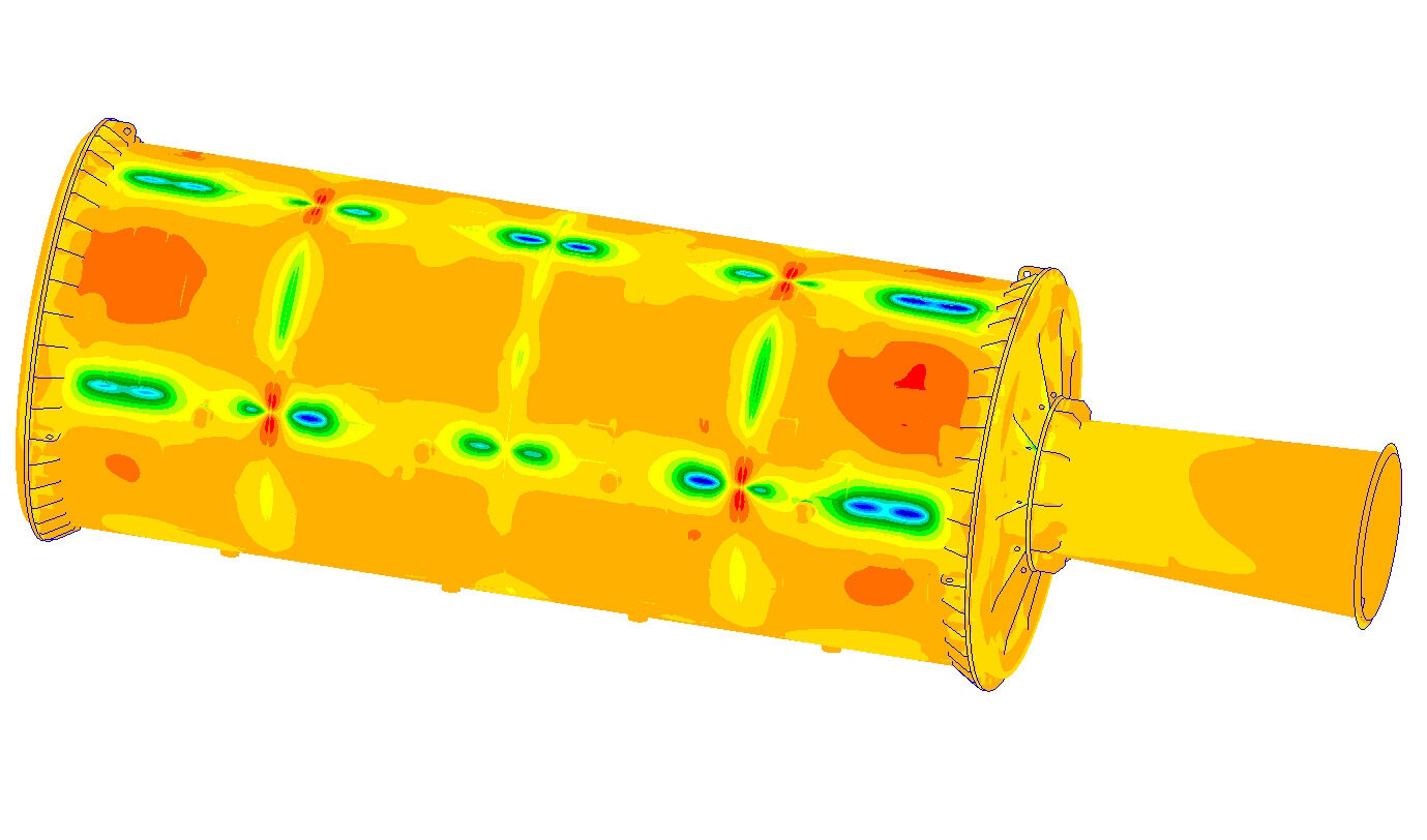
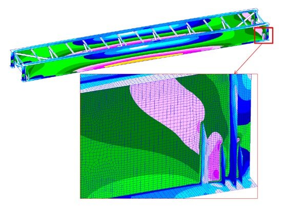
Detailed finite element analysis (FEA) was undertaken by LEC to obtain analytical stress results, which were then compared with on-site strain gauge measurements obtained by Roy Hill’s sub-contractor.  This enabled LEC to determine an actual DLA for these bridges.

THE LEC ADVANTAGE

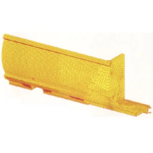
A detailed three-dimensional finite element model of the rail bridges was created by LEC in MSC.FEA using predominantly QUAD4 plate elements (four noded quadrilateral isoparametric element) and HEXA elements (eight-noded brick elements) were used to model the concrete deck. MSC.FEA is a state-of-the-art finite element analysis software package which is well-suited to this type of application.


VISUAL INSPECTION OF HEAVY HAUL RAIL BRIDGE BEARINGS

Roy_Hill_Rail_5.jpg

FOCUSING QUESTION

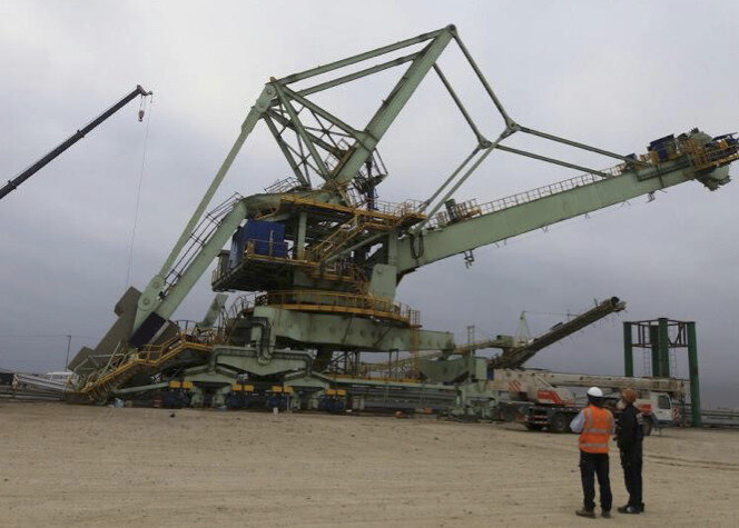
Roy Hill’s rail line has 11 steel girder rail bridges that form part of the vital link between their mine operations and port export facility, and their safe operation is reliant on the condition of the bridge bearings.

Roy_Hill_Rail_6.jpg

THE SOLUTION

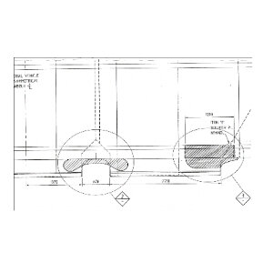
Periodic visual inspections of the bridge bearings were undertaken by LEC to monitor the deterioration rate of the bearing by means of measuring the vertical gap between the upper and lower half of the bearing.

THE LEC ADVANTAGE

The team at LEC were able to provide recommendations based on the periodic measurement data.  This allowed Roy Hill to prioritise the bearing replacement programme accordingly.


BRIDGE BEARING DESIGN REVIEW

FOCUSING QUESTION

Roy Hill are replacing the existing elastomeric pot bearings with spherical bearings and the technical aspects of this change need to be fully understood to ensure safe & reliable operation.

THE SOLUTION

Roy_Hill_Rail_7.jpg
Roy_Hill_Rail_8.png

LEC carried out a technical review of the new spherical bearing design, including reviewing the design criteria, design loads & parameters and undertaking structural design checks (such as bolt shear capacity & weld design calculations).

THE LEC ADVANTAGE

During the design review, LEC identified some anomalies in the design loads which were able to be resolved with the original bridge designer and the new bearing supplier. LEC’s dimensional reviews, based on both documentation and site measurements, ensured the new spherical bearings will fit the existing bolt arrangements.


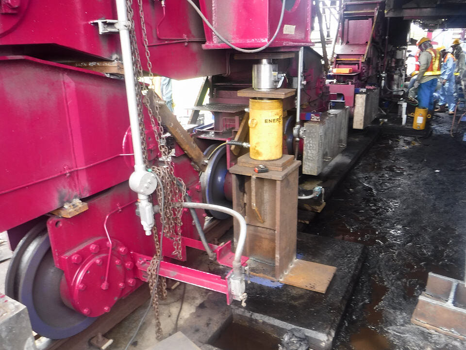
TECHNICAL ASSISTANCE DURING BEARING CHANGEOUT

Roy_Hill_Rail_9.jpg

FOCUSING QUESTION

To minimise disruption to heavy haul rail operations, the bearing changeouts were scheduled during tight shutdown windows.

THE SOLUTION

LEC provided on-site technical support for the bearing changeouts to enable quick resolution of any technical queries.

THE LEC ADVANTAGE

By collaborating with Roy Hill and their sub-contractors, LEC were able to ensure the bearing changeouts occurred on schedule and in accordance with the design intent.


SUMMARY OF SERVICES PROVIDED BY LEC TO ROY HILL

  • Structural Integrity Assessment

  • Advanced Finite Element Analysis

  • Site Inspections of Existing Bearings and Dimensional Measurements

  • Independent Review of the New Bearing Design

  • Technical Assistance during the Installation of the New Bearings


The Importance of Balancing and Weighing a Bulk Materials Handling Machine

A bucketwheel reclaimer is a balanced machine that needs weighing

During the commissioning process for a balanced mobile Bulk Materials Handling Machine (BMHM) such as a bucketwheel reclaimer, stacker, bucketwheel stacker reclaimer or shiploader, an important step is to balance and weigh the machine. Although it may be tempting to forego this vital step due to schedule demands and the impending commencement of operations, it is imperative that proper balancing and weighing be carried out to ensure the safe and reliable operation of the machine for many years to come.

Validates the Design Intent

Balancing and weighing of a new machine on site allows for comparisons to be made between the measured and design values. Any discrepancies regarding the luffing structure balance and total weight of the machine may require further investigation and rectification prior to commencement of operation. This practical validation step is an important hold point before handover. The Australian and international standards for mobile BMHM do not allow the as-constructed weight to be more than a 5% variation to the design value, in which case the design checks and calculations must be repeated.

Avoiding False Confidence

If only balancing or weighing is undertaken, and not both, this does not provide the machine’s owner a complete picture of their new investment. As an example, weighing alone might indicate the machine’s mass matches the design value. But this might give the project team a false sense of confidence, because without also undertaking appropriate balance and centre of gravity checks on-site the machine’s stability cannot be verified and it might be improperly balanced, which may not be obvious from weighing alone.

Preparing to undertake weighing of a stacker reclaimer

Achieve the Fatigue Service Life

The stability, balance and centre of gravity is critical for a machine that undertakes luffing and/or slewing motions, such as a bucketwheel reclaimer, stacker or shiploader. If the machine is not properly balanced, the fatigue stresses caused by each luffing and/or slewing motion can be amplified and the slew bearing load distributions may also be outside its design load envelope. As such, an incorrectly balanced machine will have a shortened slew bearing service life and premature onset of fatigue cracking.

 
Hydraulic jacks used to weigh a stacker reclaimer
 

Confirm Wheel Loads on Rail

The loads imposed on the wheels and rails for a bulk materials handling machine depend not only on the machine’s overall weight but also its balance and overall centre of gravity. An overweight or incorrectly balanced machine will have excessive wheel loads which can lead to wear issues for the wheels and rails. It can also mean that the long travel drive power may not be adequate for the machine to operate efficiently. These increased loads can also have significant consequences for the wharf or rail foundations, which were designed and built for a specific design wheel load spectrum.

The Best Methodology

The correct counterweight is critical for the machine balance

The best method for balancing and weighing will depend on the design and configuration of the particular machine, therefore using an incorrect methodology can give erroneous or inconclusive weight and balance results. There are many factors to consider which add together to create complexity. Taking measurements with the boom horizontal is sufficient for some machines but not for others. If the conclusion is that the machine is overweight or improperly balanced, what is the path forward? Adding or removing counterweight can have significant implications elsewhere on the machine that need to be fully understood.

In recognition of the importance of weighing and balancing, the requirement of Australian Standard AS4324.1 (2017) states that:

After a machine has been constructed, the mass and centre of gravity of the as-built machine shall be accurately determined
— Clause 5.9 of AS4324.1 (2017)

The team at LEC are experienced in preparing suitable procedures to validate the luffing structure balance and weighing of the entire machine in accordance with the requirements of AS4324.1 as well as other international standards such as ISO 5049-1 and FEM Section II (2 131 / 2 132).

Logan from LEC recording measurements from a machine weighing on-site

Click here to contact LEC and discuss the best methodology for weighing and balancing your particular bulk materials handling machine.

Return to Service of a Derailed Grab Unloader

Photo of clamshell bucket grab unloader

Due to an unforeseen event, a clamshell bucket grab unloader moved away from its parked position and derailed, causing visible damage to the pier leg and bridge structure.

The derailment of the grab unloader

The derailment resulted in an offset between the shear leg and the pier leg that caused the bridge structure to skew 10 degrees from its neutral position. This excessive skew angle resulted in contact between the pier leg and the bridge structure which caused visible structural deformation and local plate buckling. The structural damage due to this incident was investigated using three-dimensional finite element analysis (FEA) to simulate the contact condition and to compare the FEA model’s results with the detailed site survey measurements. This facilitated the calculation of the locked-in structural forces in the grab unloader at its derailed position. The buckling modes predicted by the FEA results correlated with the buckling modes visible on the derailed grab unloader.

Structural damage on the grab unloader, caused by the derailment incident.

Structural damage on the grab unloader, caused by the derailment incident.

These FEA results formed the basis for the re-railing methodology, in consultation with the heavy-lifting contractor, which involved pulling the shear leg structure to align with the pier leg structure and then lifting & rotating the pier leg structure to return the long travel wheels back onto the rail. Temporary supports were installed to ensure the safety and stability of the grab unloader during the re-railing process.

Structural plate buckling caused by the derailment incident.

Structural plate buckling caused by the derailment incident.

Once the machine was returned to its normal operating position on the rails, several repairs were necessary to remediate the structural damage caused during the derailment. The design of these structural repairs was undertaken using detailed finite element modelling and analysis (FEA) to ensure that the proposed structural repairs met or exceeded the design requirements of the original structure.

The grab unloaded was successfully returned to operation after the completion of the structural repairs and recommissioning of the mechanical, electrical and control systems.


Structural Design Review of a Tandem Rotary Tippler

FEA analysis of a rotary tippler

LEC has recently completed an independent third-party structural design review of a new tandem rotary tippler and its associated positioner and wheel grippers. The new tippler was procured in order to increase the annual export throughput of an iron ore port.

Finite element model of the tippler and positioner structures

Finite element model of the tippler and positioner structures

Typical fatigue stress range calculations

Typical fatigue stress range calculations

Detailed structural modelling and analysis was carried out independently using advanced Finite Element Analysis (FEA). Due to the cyclical motion of the tippler, design checks were focused on the fatigue service life assessment. Stress fluctuation due to the rotating motion of the tippler was calculated by analysing the tippler in several angular operating positions.

The independent design review was predominantly carried out in parallel with the Original Equipment Manufacturer’s (OEM) design process to meet the stringent project schedule. Design anomalies and structural non-conformance with the relevant design codes were promptly communicated to the OEM, thus allowing any required modification to the design to be implemented early in the design phase. This reduces the risk of potential costly production delays due to design issues and the associated on-site remedial work as well as the potential for commercial and/or legal disputes.

Tippler during transport

LEC also carried out a design review of the vertical lifting arrangement and transport saddles for land and sea transportation of the tippler cage structure, from the OEM’s fabrication yard to the owner’s site.

Fatigue Cracking of Rail Wagons

Typical heavy haul rail wagons

Consistent fatigue cracks were observed in a number of coal wagons, which had resulted in loss of revenue for the rail operator. Structural modification of the wagon body structure was required to prevent the crack from re-appearing. The main challenge on this project was to develop an effective solution while minimising the increase in wagon tare mass. Any increase in the ore wagon weight would reduce their payload and the associated revenue.

Fatigue life assessment procedure

As part of the design process, a finite element model of the wagon was created. The model incorporated sufficient details to reasonably predict the location and magnitude of stress concentrations and hence locations where fatigue cracking may initiate. Fatigue analysis was carried out in accordance with the recommendations given by the Association of American Railroads (AAR), Fatigue Design of New Freight Cars. The results from this analysis were in close agreement with the locations of the existing cracks.

Based on this assessment, a local structural strengthening solution was developed to effectively reduce the fatigue stress. The geometry of the local strengthening was optimised to minimise the weight and for ease of installation. The proposed structural modifications (<1% of the wagon tare mass) have since been successfully implemented and have extended the service life of the wagons by at least 15 years.

Service Life Extension for a Bucketwheel Reclaimer

A bucketwheel reclaimer

A bucketwheel reclaimer had been decommissioned after 25 years due to extensive structural defects, including cracking in the luffing pivot rocker region.

For these defects to be repaired, the traditional approach would be to fully dismantle the reclaimer in the reverse order to which it had been constructed, however this would require an extensive laydown area, high capacity cranage and months of construction work with the associated high risk. Another alternative would be the complete replacement with a new reclaimer, which would require a significant cost and timeframe for the procurement and commissioning of the new machine.

Instead, an in-situ structural remediation solution was undertaken which enabled the client to resume operations in 12 months, sooner than a traditional refurbishment and at a cost saving of several million Australian dollars.

Temporary supports and structural repairs to a bucketwheel reclaimer
Close-up view of structural repairs to a bucketwheel reclaimer

The major remediation works included:

  • Repair of structural cracking in the rocker arm assembly.

  • Hydraulic luffing cylinders were removed, refurbished and re-installed.

  • Slew bearing replacement.

  • Bucketwheel replacement, including shaft and drive assembly.

  • Replacement of heavily corroded structural members on bucketwheel boom.

The superstructure of the reclaimer was lifted in-situ with the boom and counterweight still assembled, which allowed the change out of the slew bearing and the repair of the rocker assembly.

This implementation required purpose-built temporary luffing cylinders, temporary support frames, and the installation of safety features such as strain gauges to monitor the loads and stability throughout the construction process.

Repair & Prevention of Cracking in an Existing Tippler

Photograph of tippler during installation

Photograph of tippler during installation

Cracks in the Cage Structure

Cracks in the Cage Structure

A number of cracks were identified in the cage structure of an existing rotary tippler, during routine site inspection, after approximately 10 years in operation. These cracks were immediately addressed using temporary repair procedures by the port operator.

While the temporary repair prevented immediate disruptions to the port operation, a long-term structural solution to the tippler cage structure was required in order to prevent similar cracks from reappearing. A conceptual structural modification was developed with the aid of Finite Element Analysis (FEA). A three-dimensional FEA model of the tippler cage structure was created and analysed to determine the extent of the highly stressed regions. This allowed the structural modification to be designed effectively and efficiently, as well as minimising the tonnage of the structural remediation work.

Comparative analysis with the existing (unmodified) tippler structure was carried out to verify the effectiveness of the structural modification. The final design solution was proposed to the port operator and the Original Equipment Manufacturer (OEM) for their acceptance and approval. The proposed structural modification has since been approved by the OEM and successfully implemented on site.

LEC’s Finite Element Analysis (FEA) Capabilities

Advanced FEA analysis by LEC

Why use FEA ?

Structures in the resource and heavy industrial sectors are often geometrically complex and cannot be readily simplified to a traditional beam/frame structural analysis approach. Advanced Finite Element Analysis (FEA) techniques facilitate a more accurate representation of plated structures and thick casting / forging components using 2-D and 3-D elements, respectively.

Examples of FEA by LEC

What FEA software does LEC use ?

LEC use MSC.FEA finite element software, which is a combination of MSC.Patran (finite element modeling pre- and post-processing software) and MSC.Nastran (finite element analysis solver). Nastran is a finite element analysis program that was originally developed for NASA, in the late 1960’s, in the United States. LEC personnel have been using MSC.Nastran software since 1992.

What FEA is not

FEA is not a silver bullet for complex structural problems. The old adage of “garbage in garbage out” is very applicable to FEA computer analyses. Proper selection of solution parameters, element types, mesh density, load & boundary constraints are essential in order to produce a reliable finite element analysis model. One also cannot underestimate the importance of the interpretation of the finite element analysis results. This interpretation skill will allow the analyst to make sound engineering decisions based on the analysis results. That is why all LEC’s advanced structural analyses using finite element modeling, analysis and design checks are carried out in-house by highly experienced and dedicated LEC specialist engineers and technologists.

Typical FEA workflow

LEC retain MSC.FEA licenses for the following advanced structural analysis:

Solution Type Typical Application on LEC’s Projects
Linear static analysis / linear buckling analysis Independent design review and development of design solution for a variety of structures in the resource and heavy industrial sectors.
Natural frequency / modal analyses Dynamic sensitive structures (e.g., stacks/chimneys), preliminary analysis for structures subjected to vibrating loads (e.g., crushers).
Transient dynamic analysis
(frequency/time domain)
Detailed dynamic analysis for structures subjected to vibrating loads
Geometric and material non-linear analysis Structural forensic investigation.

LEC’s typical finite element analysis workflow is shown in the diagram below:

LEC-FEA-Workflow.jpg

Click here to explore some of the projects completed by LEC personnel using finite element analysis.

Why do I need an independent design review?

A collapsed stacker

Every machine is unique

When procuring a new Mobile Bulk Materials Handling Machine (BMHM), such as a bucketwheel reclaimer, stacker reclaimer, stacker, bridge/portal-type reclaimer or ship loader, the machines configuration will depend on many factors:

  • Required throughput;

  • Stockpile layout and footprints;

  • Yard conveyor arrangements;

  • Bund or wharf rail gauge;

  • Properties of the material to be handled.

It would therefore be very unlikely to find an “off-the-shelf design” that would suit all the required design parameters for a particular mine or port site.

Higher rates of structural failure

A new BMHM is a major capital expenditure asset with an expected design service life of 25+ years, however, they experience a higher rate of structural failure when compared to other heavy industrial structures.

A collapsed bucketwheel reclaimer

Historical evidence shows that catastrophic structural failures can occur at any time during a machine’s service life, including during the commissioning stage.

Safety and cost benefits

Engaging an independent or third-party design reviewer during the early stages of procurement can provide many benefits:

  • Implement “Safety in Design” early in the design phase;

  • Satisfies legislative requirements (duty of care / due diligence);

  • Anomalies in the machine configuration and potential constructability issues can be identified and notified to the supplier (OEM) early in the design phase;

  • Design code compliance issues can be identified in the design phase and promptly rectified;

  • Costly production delays due to design issues and associated on-site remedial work can be minimised;

  • Identifying design issues early in the design phase minimises cost overrun and schedule delay;

  • Structural modifications can be incorporated during fabrication without undue cost or schedule penalty;

  • Minimise the risk of commercial and/or legal disputes which potentially lead to expensive litigation.

A catastrophic structural failure

Prevention is better than Remediation

LEC personnel have undertaken independent detailed design reviews, structural condition assessments and failure investigations for more than 50 bulk materials handling machines since 1993. Often this involved detailed Finite Element Analysis (FEA) using 2D and 3D elements.

Based on our experience, the detailed design review often identifies structural design issues related to:

  • Safety in Design;

  • Omissions and ambiguities in the Technical Specification documents;

  • Materials and constructability issues;

  • Serviceability issues;

  • Member strength issues;

  • Member and local plate buckling issues;

  • Fatigue service life compliance.

These design issues can generally be resolved with the Original Equipment Manufacturer (OEM) during the design phase, thus eliminating potential schedule drift and cost overruns.

An independent detailed design review can be carried out in accordance with the following standards, generally nominated in the client’s technical specification for the new Bulk Materials Handling Machine:

  • Australian Standard AS 4324.1

  • FEM Section II (2 131 / 2 132)

  • ISO 5049-1

Click here to contact LEC and discuss your requirements for an evaluation of a machine’s technical specification and an independent design review.

A failed tripper structure

Design Verification of Drum Conditioner for Lithium Plant

Finite Element Analysis (FEA) model of drum conditioner

LEC undertook finite element modelling, analyses and design verification of a drum conditioner for a lithium plant in Australia, which included:

• Design code compliance checks in accordance with AS 3990

• Buckling analysis using MSC.Nastran

• Natural frequency analysis using MSC.Nastran

• Fatigue endurance limit calculations in accordance with the requirements of BS 7608

FEA analysis results for drum conditioner

The three-dimensional geometric model was discretised using predominantly MSC Nastran’s QUAD4 plate elements (four-noded quadrilateral isoparametric element) and where necessary TRIA3 (three-noded isoparametric triangular elements). MSC Nastran’s HEXA (eight-noded isoparametric solid elements), PENTA (six-noded isoparametric solid elements) and TETRA (four-noded isoparametric solid elements) were used locally to model the tyre support region closer to the exit end diaphragm to simulate the weld details for fatigue assessment. Fine mesh was adopted in the regions where fatigue assessment was required.

As a result, a design verification report was prepared by LEC containing proposed structural modifications for compliance with the applicable codes and standards.